
Page 23 - HA
P. 23
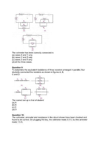
The voltmeter has been correctly connected in
               (a) cases X and Y only
               (b) cases Y and Z only
               (c) cases Z and X only
               (d) all the three cases.


               Question 9:
               To determine the equivalent resistance of three resistors arranged in parallel, four
               students connected the resistors as shown in figures A, B,
               C and D.


               The correct set-up is that of student
               (a) A
               (b) B
               (c) C
               (d) D


               Question 10:
               The voltmeter, ammeter and resistance in the circuit shown have been checked and
               found to be correct. On plugging the key, the voltmeter reads 4.5 V, but the ammeter
               reads 1.5 A.