
Page 21 - HA
P. 21
(a) circuit (I) only.
(b) circuit (II) only.
(c) both the circuits (I) and (II).
(d) neither of the two circuits.
Question 4:
A student did the experiment to find the equivalent resistance, of two given resistors,
R] and R.v first when they are connected in series and next when they are
connected in parallel. The two values of the equivalent resistance obtained by him
were Rs and R respectively. He would find that
(a) Rs > Rs
(b) Rp> Rs
(c) Rs = Rp=(R1+R2/2)
(d) Rs = Rp but not equal to (R1+R2/2)
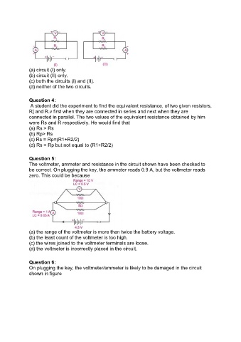
Question 5:
The voltmeter, ammeter and resistance in the circuit shown have been checked to
be correct. On plugging the key, the ammeter reads 0.9 A, but the voltmeter reads
zero. This could be because
(a) the range of the voltmeter is more than twice the battery voltage.
(b) the least count of the voltmeter is too high.
(c) the wires joined to the voltmeter terminals are loose.
(d) the voltmeter is incorrectly placed in the circuit.
Question 6:
On plugging the key, the voltmeter/ammeter is likely to be damaged in the circuit
shown in figure